4.3 Discretisation of the Convective Fluxes 对流通量的离散化[cfd-4-3]
在前几节中ï¼我们总体上讨论了空间离散方法学。在本部分中ï¼我们将更深入地了解对流通量近似的具体细节。en
In the previous sections, we discussed the spatial discretisation methodologies in general. In this part, we shall learn more about the details, how the convective fluxes can be approximated.
正如我们在3.1.5小节中已经看到的ï¼在有限体积方法的框架下ï¼基本上可以在以下几类格式中选择:
- 中心格式(central);
- 通量向量分裂格式(flux-vector splitting);
- 通量差分分裂格式(flux-difference splitting);
- 总变差减小(total variation diminishing,TVD)格式;以及
- 脉动分裂格式(fluctuation-splitting)
。为了控制篇幅ï¼我们只介绍最重要、最流行的方法;对基本格式的各种可能改型不再详细描述ï¼而是引用相关文献。en
As we could already see in Subsection 3.1.5, in the framework of the finite volume approach, we have basically the choice between:
- central,
- flux-vector splitting,
- flux-difference splitting,
- total variation diminishing (TVD), and
- fluctuation-splitting
schemes. In order to keep the amount of material bounded, we will restrict ourselves to the most important and popular methods. We will omit any detailed description of all possible modifications to the basic schemes, but instead reference the relevant literature.
在开始详细展示各种离散格式之前ï¼我们应当先解释left与right state(左状态与右状态)这两个称谓ï¼以及stencil(模板)或computational molecule(计算分子)的含义。en
Before we start to present the various discretisation schemes in detail, we should explain what is meant by the designations left and right state, as well as by stencil or computational molecule, respectively.
某些单元中心格式与对偶控制体格式需要把流动变量插值到控制体的面上。图4.8以i方向网格为例示意了这一情形。en
Certain cell-centred and dual control-volume schemes require an interpolation of flow variables to the faces of the control volume. The situation is sketched in Fig. 4.8 for a grid in the i-direction.
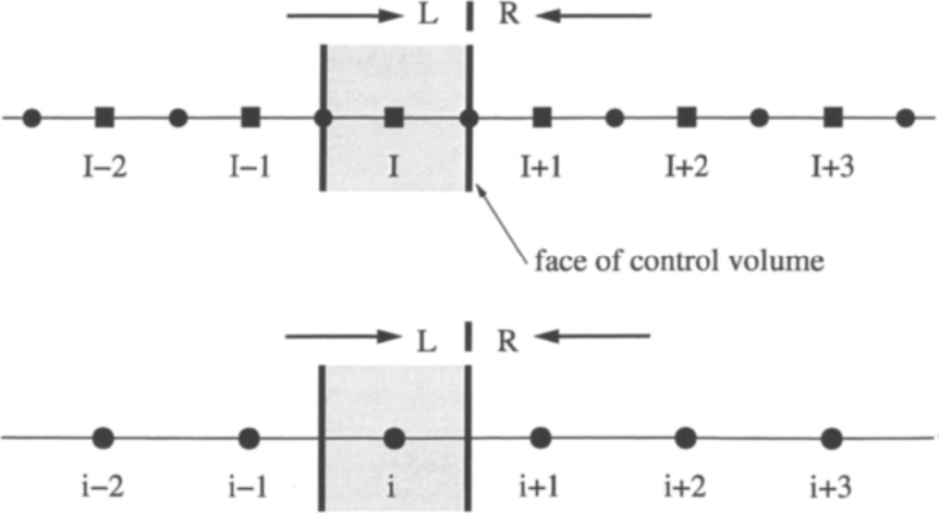
图4.8:单元面\(I+1/2\)(或\(i+1/2\))处的左状态与右状态。上半部分:单元中心格式;下半部分:采用对偶控制体的单元顶点格式。图例:圆点表示节点ï¼矩形表示单元形心;L与R分别表示面左侧与右侧的状态ï¼箭头所指为控制体的面(face of control volume)。
中心格式(见下一小节)采用的一种做法ï¼是利用面两侧相同数目的值做线性插值;换句话说ï¼插值相对于面居中。基于欧拉方程特征的离散——上风格式——则用非对称公式分别从面的左侧和右侧插值流动变量。这两个值分别称为左状态(left state)和右状态(right state)ï¼随后被用来计算通过该面的对流通量(见方程(4.18)、(4.23)、(4.38)或(4.43))。这些插值公式几乎全部(TVD格式除外)基于Van Leer的MUSCL(守恒律的单调上游中心型格式,Monotone Upstream-Centred Schemes for Conservation Laws)方法[29]。对于一般流动变量\(U\)ï¼它们为en
One possibility, which is employed by the central scheme (see next subsection), consists of linear interpolation using the same number of values to the left and to the right of the face. In other words, the interpolation is centred at the face. Discretisations based on the characteristics of the Euler equations - upwind schemes - separately interpolate flow variables from the left and the right side of the face using non-symmetric formulae. The two values, named the left and the right state, are then utilised to compute the convective flux through the face (see Eqs. (4.18), (4.23), (4.38), or (4.43)). The interpolation formulae are almost exclusively (with the exception of TVD schemes) based on Van Leer's MUSCL (Monotone Upstream-Centred Schemes for Conservation Laws) approach [29]. They read for a general flow variable \(U\)
前向(\(\Delta_{+}\))与后向(\(\Delta_{-}\))差分算子定义为en
The forward (\(\Delta_{+}\)) and the backward (\(\Delta_{-}\)) difference operators are defined as
指标按需平移。若把节点指标\(i\)替换\(I\)ï¼上述关系式对采用对偶控制体的单元顶点格式仍然成立。参数\(\epsilon\)可取为零ï¼得到一阶精度的上风离散。参数\(\hat{\kappa}\)决定插值的空间精度。当\(\epsilon = 1\)、\(\hat{\kappa} = -1\)时ï¼上述插值公式(4.46)给出完全单侧的流动变量插值ï¼在均匀网格上得到二阶精度的上风近似。\(\hat{\kappa} = 0\)对应二阶精度的上风偏置线性插值。此外ï¼取\(\hat{\kappa} = 1/3\)可得三点插值公式ï¼它(在有限体积框架下——参见文献[30]、[48])构成二阶上风偏置格式ï¼其截断误差低于\(\hat{\kappa} = -1\)与\(\hat{\kappa} = 0\)的格式。最后ï¼若指定\(\hat{\kappa} = 1\),MUSCL方法退化为纯中心格式——即变量的算术平均。实践中最常用的是\(\hat{\kappa} = 0\)与\(\hat{\kappa} = 1/3\)的格式。en
The indices are shifted as appropriate. The above relationships remain valid for a cell-vertex scheme with dual control volumes, if the node index \(i\) is substituted for \(I\). The parameter \(\epsilon\) can be set equal to zero to obtain a first-order accurate upwind discretisation. The parameter \(\hat{\kappa}\) determines the spatial accuracy of the interpolation. For \(\epsilon = 1\) and \(\hat{\kappa} = -1\), the above interpolation formulae (4.46) give a fully one-sided interpolation of the flow variables, which results in a second-order accurate upwind approximation on uniformly spaced grid. The case \(\hat{\kappa} = 0\) corresponds to a second-order accurate, upwind-biased linear interpolation. Furthermore, by setting \(\hat{\kappa} = 1/3\), we obtain a three-point interpolation formula which constitutes (in a finite volume framework - cf. Ref. [30], [48]) a second-order upwind-biased scheme with lower truncation error than the \(\hat{\kappa} = -1\) and \(\hat{\kappa} = 0\) schemes. Finally, if we specify \(\hat{\kappa} = 1\), the MUSCL approach reduces to a purely central scheme - the average of variables. The schemes with \(\hat{\kappa} = 0\) and \(\hat{\kappa} = 1/3\) are the most often used ones in practice.
当流动区域包含强梯度时,MUSCL插值(4.46)必须辅以所谓的限制器函数(limiter function)或限制器(limiter)。限制器的目的是抑制解的非物理振荡。限制器将在4.3.5小节进一步讨论。en
The MUSCL interpolation (4.46) has to be enhanced by the so-called limiter function or limiter, if the flow region contains strong gradients. The purpose of the limiter is to suppress non-physical oscillation of the solution. Limiters will be discussed further in Subsection 4.3.5.
模板(stencil)或计算分子(computational molecule)指参与残差、梯度等计算的那些单元形心或网格点的并集。例如ï¼若分别按方程(4.15)、(4.20)或(4.35)、(4.40)对控制体各面上的通量作平均ï¼则在二维得到5点模板ï¼由下列单元/点组成en
Stencil or computational molecule stands for the union of those cell-centroids or grid points, which are involved in the computation of the residual, the gradient, etc. For example, if we average the fluxes at the faces of the control volume according to the Equations (4.15), (4.20), or (4.35), (4.40), respectively, we obtain in two dimensions a 5-point stencil, consisting of the cells/points
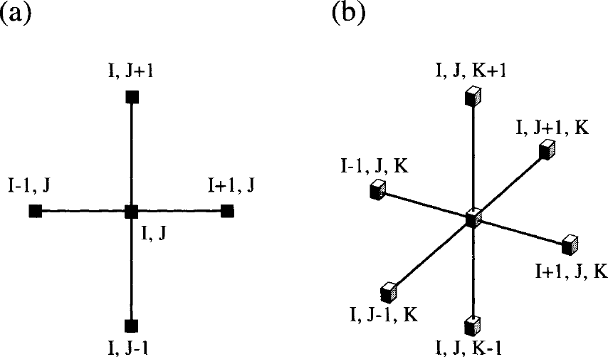
图4.9:中心离散格式的模板(计算分子):(a)二维;(b)三维空间。图例:情形(a)中模板点为\(I,J\)、\(I+1,J\)、\(I-1,J\)、\(I,J+1\)、\(I,J-1\);情形(b)中模板点为\(I,J,K\)、\(I+1,J,K\)、\(I-1,J,K\)、\(I,J+1,K\)、\(I,J-1,K\)、\(I,J,K+1\)、\(I,J,K-1\);中心点为\(I,J\)或\(I,J,K\)。
在三维中ï¼得到7点模板ï¼涉及的单元/点为en
In three dimensions, a 7-point stencil results, which involves the cells/points
两种模板均示于图4.9。注意ï¼在笛卡尔网格上ï¼这对应于i、j、k方向一阶导数的二阶精度中心差分近似。因此ï¼把采用中心差分的有限差分格式应用于控制方程的微分形式ï¼将得到相同的结果。en
Both stencils are displayed in Fig. 4.9. Note that on a Cartesian grid this corresponds to the second-order accurate central-difference approximation of the first derivatives in i-, j-, and k-direction. Thus, a finite difference scheme, applied to the differential form of the governing equations and using the central differences, would deliver the same result.
4.3.1 Central Scheme with Artificial Dissipation 含人工耗散的中心格式[cfd-4-3-1]
与其他离散方法相比ï¼含人工耗散的中心格式非常简单。它既容易与单元中心格式结合实现ï¼也容易与两种单元顶点格式结合实现。因此该格式得到了非常广泛的应用。en
The central scheme with artificial dissipation is very simple compared to other discretisation methods. It is easy to implement with either the cell-centred scheme or with both cell-vertex schemes. For these reasons the scheme became very wide-spread.
中心格式的基本思想ï¼是用面两侧守恒变量的算术平均来计算控制体面上的对流通量。由于这会导致解的奇偶失联(odd-even decouplingï¼即离散方程产生两个独立的解)以及激波处的过冲ï¼为保证稳定性必须加入人工耗散(其形式与黏性通量类似)。该格式由Jameson等人[6]最先实现于欧拉方程。以作者姓氏命名ï¼它也简称为JST格式。en
The basic idea of the central scheme is to compute the convective fluxes at a face of the control volume from the arithmetic average of the conservative variables on both sides of the face. Since this would allow for odd-even decoupling of the solution (generation of two independent solutions of the discretised equations) and for overshoots at shocks, artificial dissipation (which is similar to the viscous fluxes) has to be added for stability. The scheme was first implemented for the Euler equations by Jameson et al. [6]. Because of the names of the authors, it is also abbreviated as the JST scheme.
与上风格式等相比ï¼中心格式在间断和边界层的分辨率方面一般较差ï¼但计算代价要低得多。因此ï¼人们尝试在保持数值开销较低的同时提高格式精度。例如ï¼有改进方案用于减少边界层内的人工耗散量[31]、[32]ï¼或增强激波分辨率[33]-[35]。文献[35]中的另一个想法是利用对流通量的Jacobian矩阵ï¼使每个守恒方程的耗散得到各自独立的缩放。这一成功的方法称为矩阵耗散格式(matrix dissipation scheme)ï¼可视为原始标量格式与上风格式之间的折中。基本格式还采用单一的、基于压力的传感器ï¼在间断处从二阶精度切换到一阶精度ï¼以防止流动变量的非物理振荡。文献[36]中,Jameson提出了称为SLIP(对称限制正,Symmetric Limited Positive)格式的概念ï¼其中对每个守恒方程分别施加限制器。文献[37]简要描述了上述各种方法ï¼并给出了无黏与黏性二维流动的比较结果。en
The central scheme is generally less accurate in the resolution of discontinuities and boundary layers than, let say, the upwind schemes. However, it is computationally considerably cheaper. Therefore, attempts were made to improve the accuracy of the scheme, while still keeping the numerical effort low. For example, improvements were devised to reduce the amount of the artificial dissipation in boundary layers [31], [32], or to enhance the shock resolution [33]-[35]. Another idea, followed in [35], is to utilise the Jacobian matrix of the convective fluxes, in order to scale the dissipation independently for each conservation equation. This successful approach is known as the matrix dissipation scheme. It can be viewed as a compromise between the original scalar scheme and the upwind schemes. The basic scheme also employs a single, pressure-based sensor to switch from second- to first-order accuracy at discontinuities to prevent non-physical oscillations of the flow variables. In [36], Jameson developed a concept called the SLIP (Symmetric Limited Positive) scheme, where a limiter is applied separately for each conservation equation. A brief description of the previous approaches and comparisons for inviscid and viscous 2-D flows was presented in [37].
Scalar Dissipation Scheme 标量耗散格式
通过控制体面的对流通量(方程(2.21))用变量的平均来近似ï¼分别依照方程(4.16)、(4.21)、(4.36)或(4.41)。然后ï¼为使格式稳定ï¼在中心通量上加入人工耗散[6]、[38]。于是ï¼面\((I+1/2,J,K)\)上的总对流通量为en
The convective fluxes (Eq. (2.21)) through a face of the control volume are approximated using the average of variables, according to the Equations (4.16), (4.21), (4.36), or (4.41), respectively. Artificial dissipation is then added to the central fluxes for stability [6], [38]. Thus, the total convective flux at face \((I+1/2,J,K)\) reads
其中流动变量取平均为(另见图4.8)en
where the flow variables are averaged as (see also Fig. 4.8)
在采用对偶控制体的单元顶点格式情形ï¼将改用节点指标\((i,j,k)\)。为简便起见ï¼今后把\((I+1/2,J,K)\)缩写为\((I+1/2)\)。人工耗散通量由自适应的二阶与四阶差分的混合构成ï¼它们来自一阶与三阶差分算子之和en
In the case of the cell-vertex scheme with dual control volumes, node indices \((i,j,k)\) would be used instead. For simplicity, \((I+1/2,J,K)\) will be abbreviated as \((I+1/2)\) hereafter. The artificial dissipation flux consists of a blend of adaptive second- and fourth-order differences, which result from the sum of first- and third-order difference operators
由方程(4.50)可见ï¼该格式在二维具有紧凑的9点模板ï¼在三维为13点模板。耗散用所有坐标方向上对流通量Jacobian的谱半径之和来缩放en
From Eq. (4.50) we can see that the scheme possesses a compact 9-point stencil in two dimensions and a 13-point stencil in three dimensions. The dissipation is scaled by the sum of the spectral radii of the convective flux Jacobians in all coordinate directions
单元面\((I+1/2)\)处的谱半径——例如I方向(以上标\(I\)表示)——由平均得到en
The spectral radius at the cell face \((I+1/2)\), e.g., in I-direction (represented by the superscript \(I\)), results from the average
它用下式计算en
It is evaluated using the formula
其中\(V\)为逆变量速度(contravariant velocity)(2.22),\(c\)为声速。格式用一个基于压力的传感器在激波处关闭四阶差分——在那里四阶差分会引起解的强烈振荡;该传感器同时在流场光滑区域关闭二阶差分ï¼以把耗散降到尽可能低的水平。据此ï¼方程(4.50)中的系数\(\epsilon^{(2)}\)与\(\epsilon^{(4)}\)定义为en
where \(V\) stands for the contravariant velocity (2.22) and \(c\) for the speed of sound, respectively. A pressure-based sensor is used to switch off the fourth-order differences at shocks, where they would lead to strong oscillation of the solution. The sensor also switches off the second-order differences in smooth parts of the flow field, in order to reduce the dissipation to the lowest possible level. Herewith, the coefficients \(\epsilon^{(2)}\) and \(\epsilon^{(4)}\) in Eq. (4.50) are defined as
其中压力传感器为en
with the pressure sensor given by
参数的典型取值为\(k^{(2)} = 1/2\)与\(1/128 \le k^{(4)} \le 1/64\)。为了减少跨越黏性剪切层的人工耗散量ï¼可以把方程(4.50)中的缩放因子重新定义如下[31]、[32]en
Typical values of the parameters are \(k^{(2)} = 1/2\) and \(1/128 \le k^{(4)} \le 1/64\). In order to reduce the amount of artificial dissipation across a viscous shear layer, we can re-define the scaling factors in Eq. (4.50) as follows [31], [32]
参数\(\sigma\)通常取1/2或2/3。这一表述减小了沿控制体较短一侧方向的耗散项缩放ï¼适用于较长一侧与流动方向一致的情形。en
The parameter \(\sigma\) is usually set equal to 1/2 or 2/3. This formulation decreases the scaling of the dissipation terms in the direction along the shorter side of a control volume, whose longer side is aligned with the flow.
Matrix Dissipation Scheme 矩阵耗散格式
为了通过减少数值耗散来提高精度ï¼可以把前述JST格式修改得更像上风格式。其想法是用一个矩阵——对流通量Jacobian——代替标量值\(\hat{\Lambda}^{S}\)来缩放耗散项[35]。这样ï¼每个方程都由相应的特征值恰当地缩放。于是ï¼方程(4.50)变为en
In order to improve the accuracy by reducing the numerical dissipation, the preceding JST scheme can be modified to become more like an upwind scheme. The idea is to use a matrix - the convective flux Jacobian - instead of the scalar value \(\hat{\Lambda}^{S}\) to scale the dissipation terms [35]. In this way, each equation is scaled properly by the corresponding eigenvalue. Hence, the Eq. (4.50) becomes
缩放矩阵对应于用特征值绝对值对角化的对流通量Jacobian\((\bar{A}_c = \partial\vec{F}_c/\partial\vec{W})\)en
The scaling matrix corresponds to the convective flux Jacobian \((\bar{A}_c = \partial\vec{F}_c/\partial\vec{W})\) diagonalised with absolute values of the eigenvalues
右特征向量矩阵\((\bar{T})\)与左特征向量矩阵\((\bar{T}^{-1})\)以及特征值对角矩阵\(\bar{\Lambda}_c\)见附录A.11。在驻点和声速线处必须对特征值加以限制ï¼以防耗散变为零。文献[35]给出了一种高效计算\(|\bar{A}_c|\)与\(\vec{W}\)乘积的方法。注意ï¼若取\(\epsilon^{(2)} = 1/2\)、\(\epsilon^{(4)} = 0\)ï¼则得到一阶精度的完全上风格式。en
The matrices of right \((\bar{T})\) and left \((\bar{T}^{-1})\) eigenvectors as well as the diagonal matrix of the eigenvalues \(\bar{\Lambda}_c\) can be found in the Appendix A.11. The eigenvalues must be limited at stagnation points and sonic lines to prevent the dissipation from becoming zero. An efficient way of computing the product of \(|\bar{A}_c|\) with \(\vec{W}\) is provided in [35]. It should be noted that by setting \(\epsilon^{(2)} = 1/2\) and \(\epsilon^{(4)} = 0\), we obtain a first-order accurate, fully upwind scheme.
如前所述ï¼这里的目标是发展一种精度接近上风格式、但计算开销只比标量耗散方法高约15%-20%的格式。最近ï¼文献[37]报道了与通量向量分裂格式(CUSP与AUSM)的比较结果。en
As it was already stated before, the idea here was to develop a scheme which accuracy is close to that of upwind schemes, but which is still computationally only slightly more expensive (about 15-20%) than the scalar dissipation approach. Results of comparisons with flux-vector splitting schemes (CUSP and AUSM) were recently reported in [37].
4.3.2 Flux-Vector Splitting Schemes 通量向量分裂格式[cfd-4-3-2]
通量向量分裂方法可以视为最初等的上风格式ï¼因为它们只考虑波的传播方向。通量向量分裂格式把对流通量向量分解为两部分——或按某些特征变量的符号ï¼或分裂为对流部分与压力部分。著名的Van Leer通量向量分裂格式[39]属于基于特征分解的第一类。遵循第二种思路的有较新的方法ï¼如Liou等人的对流上游分裂方法(AUSM)[40]、[41]ï¼以及Jameson的对流上游分裂压力(CUSP)格式[42]、[43]。类似的方法还有Edwards提出的低耗散通量分裂格式(LDFSS)[44]ï¼以及Rossow的基于马赫数的对流压力分裂(MAPS)格式[45]、[46]。en
The flux-vector splitting methods can be viewed as the first level of upwind schemes, since they account only for the direction of wave propagation. The flux-vector splitting schemes decompose the vector of the convective fluxes into two parts - either according to the sign of certain characteristic variables, or into a convective and a pressure part. The well-known Van Leer's flux-vector splitting scheme [39] belongs to the first category based on characteristic decomposition. The second approach is followed by more recent methods like the Advection Upstream Splitting Method (AUSM) of Liou et al. [40], [41], or the Convective Upwind Split Pressure (CUSP) scheme of Jameson [42], [43], respectively. Further similar approaches are the Low-Diffusion Flux-Splitting Scheme (LDFSS) introduced by Edwards [44], or the Mach number-based Advection Pressure Splitting (MAPS) scheme of Rossow [45], [46].
通量向量分裂格式只能在单元中心格式(4.2.1小节)或采用对偶控制体的单元顶点格式(4.2.3小节)的框架下实现。与采用标量人工耗散的中心格式相比ï¼其优点在于数值开销只是适度增加ï¼而激波与边界层的分辨率却好得多。不过ï¼矩阵耗散格式(方程(4.58))也能给出精度相当的结果[37]。由于某些数值上的困难ï¼多位研究者对基本格式(尤其是AUSM)作了大量改进ï¼相关工作至今仍在继续。下面我们将介绍Van Leer、AUSM与CUSP格式的基础ï¼对最重要的改进给出一些提示ï¼并提供相应文献。en
The flux-vector splitting schemes can be implemented only in the framework of the cell-centred scheme (Subsection 4.2.1), or the cell-vertex scheme with dual control volumes (Subsection 4.2.3). Their advantage can be seen in only a moderately increased numerical effort but a much better resolution of shocks and boundary layers, as compared to the central scheme with scalar artificial dissipation. However, the matrix dissipation scheme (Eq. (4.58)), can also produce results of comparable accuracy [37]. Because of certain numerical difficulties, many modifications to the basic schemes (particularly to AUSM) were devised by various researchers and the development still continues. In the following, we shall present the basics of the Van Leer, AUSM and CUSP schemes, give some hints with respect to the most important modifications, and provide references to the corresponding literature.
Van Leer's Scheme Van Leer格式
Van Leer的通量向量分裂格式[39]基于对流通量的特征分解。该方法在贴体网格上的推广见文献[47]、[48]。对流通量被分裂为正、负两部分ï¼即en
Van Leer's flux-vector splitting scheme [39] is based on characteristic decomposition of the convective fluxes. An extension of the approach to body-fitted grids was presented in [47], [48]. The convective flux is split into a positive and a negative part, i.e.,
分解依据的是垂直于控制体面的马赫数(例如在\((I+1/2)\)处——见图4.8)en
according to the Mach number normal to the face of the control volume (e.g., at \((I+1/2)\) - see Fig. 4.8)
其中\(V\)为逆变量速度(2.22),\(c\)为声速。在采用对偶控制体的单元顶点格式情形ï¼单元指标须换成节点指标。流动变量\(\rho\)、\(u\)、\(v\)、\(w\)与\(p\)的值须先按方程(4.19)或方程(4.39)插值到控制体的面上。然后ï¼正通量用左状态计算ï¼负通量用右状态计算。对流马赫数\((M_n)_{I+1/2}\)由以下关系得到[39]en
where \(V\) represents the contravariant velocity (2.22) and \(c\) the speed of sound, respectively. In the case of the cell-vertex scheme with dual control volumes, the cell indices have to be replaced by node indices. The values of the flow variables \(\rho\), \(u\), \(v\), \(w\), and \(p\), respectively, have to be interpolated first to the faces of the control volume correspondingly to Eq. (4.19) or Eq. (4.39). Then, the positive fluxes are computed with the left state and the negative fluxes with the right state. The advection Mach number \((M_n)_{I+1/2}\) is obtained from the relation [39]
其中分裂马赫数定义为en
where the split Mach numbers are defined as
而en
and
马赫数\(M_L\)与\(M_R\)分别用左、右状态计算ï¼即en
The Mach numbers \(M_L\) and \(M_R\) are evaluated using the left and right state, respectively, i.e.,
当\(|M_n| < 1\)(亚声速流动)时ï¼正、负通量部分为en
In the case of \(|M_n| < 1\) (subsonic flow), the positive and the negative flux parts are given by
质量与能量通量分量定义为en
The mass and energy flux components are defined as
对于超声速流动ï¼即\(|M_n| \ge 1\)ï¼通量按下式计算en
For supersonic flow, i.e., for \(|M_n| \ge 1\), the fluxes are evaluated from
左、右状态的计算一般遵循MUSCL方法[29]ï¼即方程(4.46)。若流场含有激波等间断ï¼高阶格式\(\hat{\kappa} = -1\)、\(\hat{\kappa} = 0\)与\(\hat{\kappa} = 1/3\)都需要限制器。更多细节见4.3.5小节。en
The evaluation of the left and right state follows generally the MUSCL approach [29], which is given by Eqs. (4.46). The higher order schemes \(\hat{\kappa} = -1\), \(\hat{\kappa} = 0\) and \(\hat{\kappa} = 1/3\), respectively, require a limiter if the flow field contains discontinuities like shocks. More details are provided in Subsection 4.3.5.
Van Leer的通量向量分裂格式在欧拉方程情形下表现非常好。但用Navier-Stokes方程进行的若干研究[49]、[50]表明ï¼动量方程与能量方程中的分裂误差会抹平边界层ï¼并导致驻点温度与壁面温度不准确。为此ï¼文献[51]建议对垂直于边界层方向的动量通量作修改;文献[52]对能量通量提出了类似的补救措施。两项修改合在一起可以消除分裂误差ï¼从而显著提高解的精度[53]。en
The flux-vector splitting scheme of Van Leer performs very well in the case of the Euler equations. But several investigations [49], [50], carried out with the Navier-Stokes equations revealed that splitting errors in the momentum and the energy equations smear the boundary layers and also lead to inaccurate stagnation and wall temperatures. A modification to the momentum flux in the direction normal to the boundary layer was therefore suggested in Ref. [51]. A similar remedy for the energy flux was proposed in Ref. [52]. Both modifications together remove the splitting errors, and hence they improve the solution accuracy considerably [53].
AUSM
对流上游分裂方法(AUSM)由Liou与Steffen[40]以及Liou[54]提出。随后经Wada与Liou[55]修改并更名为AUSMD/V。最后,Liou[41]、[56]提出了称为AUSM+的改进版本。en
+的改进版本。enThe Advection Upstream Splitting Method (AUSM) was introduced by Liou and Steffen [40], and Liou [54]. It was subsequently modified by Wada and Liou [55] and renamed as AUSMD/V. Finally, an improved version termed AUSM+ was presented by Liou [41], [56].
该方法的基本思想基于这样的观察:对流通量向量(2.21)由两个物理上截然不同的部分组成ï¼即对流部分与压力部分en
The underlying idea of the approach is based on the observation that the vector of convective fluxes (2.21) consists of two physically distinct parts, namely the convective and the pressure part
方程(4.69)中的第一项代表由逆变量速度\(V\)输运的标量量;相比之下ï¼压力项由声波速度支配。现在的想法是:根据\(V\)的符号(即使在亚声速流动中)以纯上风方式离散对流项ï¼即取左状态或右状态之一;而压力项在亚声速情形下同时包含两个状态ï¼只有在超声速流动中才变为完全上风。en
The first term in Eq. (4.69) represents scalar quantities, which are convected by the contravariant velocity \(V\). By contrast, the pressure term is governed by the acoustic wave speed. The idea now is to discretise the convective term in purely upwind manner by taking either the left or the right state, depending on the sign of \(V\) (even for subsonic flow). On the other hand, the pressure term includes both states in the subsonic case. It becomes fully upwind only for a supersonic flow.
遵循文献[40]的基本AUSMï¼我们由方程(4.61)引入对流马赫数\((M_n)_{I+1/2}\)。据此ï¼可以把控制体面\((I+1/2)\)或\((i+1/2)\)处的对流通量改写为en
Following the basic AUSM from [40], we introduce an advection Mach number \((M_n)_{I+1/2}\) from Eq. (4.61). Herewith, we can recast the convective flux at the face \((I+1/2)\), or \((i+1/2)\) of the control volume, respectively, into
其中en
where
与Van Leer通量向量分裂格式类似ï¼对流马赫数按关系式(4.62)与(4.63)-(4.65)由左、右分裂马赫数之和求出。左、右状态(流动量:\(\rho\)、\(u\)、\(v\)、\(w\)、\(p\)、\(H\))的计算同样依据方程(4.19)或方程(4.39)分别插值到控制体的面上ï¼插值遵循方程(4.46)给出的MUSCL方法[29]。所有高阶MUSCL格式(\(\hat{\kappa} = -1\)、\(\hat{\kappa} = 0\)与\(\hat{\kappa} = 1/3\))在流场包含激波等强梯度时都需要限制器。更多细节请参阅4.3.5小节。en
Similar to Van Leer's flux-vector splitting scheme, the advection Mach number is evaluated as a sum of the left and right split Mach numbers according to the relations (4.62) and (4.63)-(4.65). The computation of the left and right state (flow quantities: \(\rho\), \(u\), \(v\), \(w\), \(p\), \(H\)) is based again on a separate interpolation to the faces of the control volume according to Eq. (4.19) or Eq. (4.39). The interpolation follows the MUSCL methodology [29], as it is given in Eq. (4.46). All higher-order MUSCL schemes (\(\hat{\kappa} = -1\), \(\hat{\kappa} = 0\), and \(\hat{\kappa} = 1/3\)) require a limiter, if the flow field contains strong gradients like shocks. Please refer to Subsection 4.3.5 for more details.
控制体面\((I+1/2)\)处的压力由分裂式[40]得到en
The pressure at the face \((I+1/2)\) of the control volume is obtained from the splitting [40]
其中分裂压力由文献[39]给出en
with the split pressures given by [39]
而en
and
当\(|M_{L/R}| < 1\)时ï¼也可以采用如下低阶展开en
It is also possible to use the following lower-order expansion for \(|M_{L/R}| < 1\)
应当指出,AUSM也可以写成如下形式en
It should be noted that we can write AUSM also in the form
方程(4.76)右端第一项代表左、右状态的马赫数加权平均——分别类似于通量平均方程(4.15)、(4.20)或(4.35)、(4.40)。第二项具有耗散性质ï¼由标量值\(|(M_n)_{I+1/2}|\)缩放。en
The first term on the right-hand side of the above Eq. (4.76) represents a Mach number-weighted average of the left and right state - similar to the average of fluxes Eq. (4.15), (4.20) or Eq. (4.35), (4.40), respectively. The second term has a dissipative character. It is scaled by the scalar value \(|(M_n)_{I+1/2}|\).
实践证明,AUSM能清晰分辨强激波ï¼并给出精确的边界层结果。然而ï¼人们发现原始AUSM[40]、[54]在激波处以及流动与网格对齐的情形会产生局部压力振荡[57]。因此文献[57]、[58]建议在激波处切换到Van Leer格式。当对流马赫数\((M_n)_{I+1/2}\)趋于零时ï¼方程(4.76)中的耗散项也趋于零ï¼因而任何扰动都无法被格式阻尼。为解决流动对齐问题ï¼文献[57]建议如下修改耗散项的缩放en
AUSM proved to deliver a crisp resolution of strong shocks and accurate results for boundary layers. However, the original AUSM [40], [54] was found to generate local pressure oscillations at shocks and in cases where the flow is aligned with the grid [57]. In [57], [58] it was therefore suggested to switch at shocks to Van Leer's scheme. When the advection Mach number \((M_n)_{I+1/2}\) tends to zero, the dissipation term in Eq. (4.76) will approach zero as well. Thus, any disturbances cannot be damped by the scheme. In order to solve the flow alignment problem, it was proposed in [57] to modify the scaling of the dissipation term as follows
其中\(\delta\)是一个小值\((0 < \delta \le 0.5)\)。这样ï¼数值耗散总是足够的。为了保持AUSM对边界层的精度ï¼可以按照与中心格式方程(4.57)相同的思路ï¼在壁面法向减小参数\(\delta\)。文献[41]、[56]针对激波附近更好的表现提出了基本AUSM的进一步改进ï¼称为AUSM+。这些修改包括新的马赫数分裂与压力分裂ï¼分别取代关系式(4.63)、(4.64)与(4.73)、(4.74)。en
+。这些修改包括新的马赫数分裂与压力分裂ï¼分别取代关系式(4.63)、(4.64)与(4.73)、(4.74)。enwhere \(\delta\) is a small value \((0 < \delta \le 0.5)\). Hence, there will always be a sufficient amount of numerical dissipation. In order to retain the accuracy of AUSM for boundary layers, the parameter \(\delta\) could be reduced in the wall normal direction using the same idea as given for the central scheme by Eq. (4.57). Further improvements of the basic AUSM, with respect to better behaviour in the vicinity of shocks, was presented in [41], [56] as AUSM+. The modifications consist of new Mach and pressure splittings, which replace the relations (4.63), (4.64) and (4.73), (4.74), respectively.
CUSP Scheme CUSP格式
对流上游分裂压力(CUSP)格式的概念与AUSM十分相似。不过,CUSP方法的优点是可以表述为通量平均(但不像AUSM那样加权)减去一个耗散项。这一特点对于在显式混合多步格式中的实现至关重要。此外ï¼由于缩放因子与AUSM不同,CUSP格式在流动对齐情形下表现更为有利。CUSP格式由Jameson[42]、[59]、[60]提出ï¼随后由Tatsumi等人[43]、[61]修改。它既可在单元中心型空间离散中实现ï¼也可在(单元顶点)对偶控制体型空间离散中实现。en
The concept of the Convective Upwind Split Pressure (CUSP) scheme is quite similar to that of AUSM. However, the CUSP approach has the advantage to be formulated as an average of fluxes (but without weighting like within AUSM) minus a dissipation term. This feature is crucial for the implementation in an explicit, hybrid multistage scheme. Furthermore, because of the different scaling factors as compared to AUSM, the CUSP scheme behaves more favourably in the case of flow alignment. The CUSP scheme was introduced by Jameson [42], [59], [60], and subsequently modified by Tatsumi et al. [43], [61]. It can be implemented either within the cell-centred or the (cell-vertex) dual control-volume type of spatial discretisation.
通过控制体面的对流通量(方程(2.21))用通量的算术平均近似ï¼分别依照方程(4.15)、(4.20)、(4.35)或(4.40)。然后ï¼为使格式稳定ï¼从中心通量中减去耗散项。于是ï¼面\((I+1/2)\)处的总对流通量为en
The convective fluxes (Eq. (2.21)) through a face of the control volume are approximated using the arithmetic average of fluxes according to the Equations (4.15), (4.20), (4.35), or (4.40), respectively. The dissipation term is then subtracted from the central fluxes for stabilisation. Thus, the total convective fluxes at the face \((I+1/2)\) read
在对偶控制体离散的情形ï¼则相应使用\((i+1/2)\)。耗散项由状态向量之差与通量向量之差的线性组合构成ï¼可表示为en
In the case of the dual control-volume discretisation, \((i+1/2)\) would apply instead. The dissipation term, which is composed of a linear combination of the differences of the state and the flux vector, can be expressed as
方程(4.79)中的\(\phi\)项有两种选择:或取总能量\(E\)ï¼或取总焓\(H\)。第一种情形称为E-CUSP格式[62]ï¼第二种相应称为H-CUSP格式。\(\phi = H\)的表述保持总焓不变[43]ï¼因而适用于无黏流动。左(\(L\))、右(\(R\))状态的计算与MUSCL方法[29]类似ï¼采用限制插值(4.118)-(4.121)。方程(4.79)中的两个因子\(\alpha^{*}c\)与\(\beta\)定义为en
There are two choices for the term \(\phi\) in Eq. (4.79). Either, \(\phi\) is set equal to the total energy \(E\), or it is set to the total enthalpy \(H\). In the first case we speak of the E-CUSP scheme [62], the second choice is consequently called the H-CUSP scheme. The formulation with \(\phi = H\) preserves the total enthalpy [43] and is therefore suitable for inviscid flows. The left (\(L\)) and right (\(R\)) state is evaluated similarly to the MUSCL approach [29], using the limited interpolation (4.118)-(4.121). The two factors \(\alpha^{*}c\) and \(\beta\) in Eq. (4.79) are defined as
而en
and
计算\(M_n\)所用的声速\(c\)同样由算术平均量得到。方程(4.80)、(4.81)中的正、负特征值\(\Lambda^{+}\)与\(\Lambda^{-}\)是所谓Roe矩阵(Roe matrix)[63]的特征值,Roe矩阵将在4.3.3小节讨论。特征值为[60]en
The speed of sound \(c\) in the evaluation of \(M_n\) is also obtained from arithmetically averaged quantities. The positive and negative eigenvalues \(\Lambda^{+}\) and \(\Lambda^{-}\) in Eqs. (4.80), (4.81) are those of the so-called Roe matrix [63], which will be discussed in the Subsection 4.3.3. The eigenvalues are given by [60]
其中\(\tilde{V}\)表示逆变量速度,\(\gamma\)为比热比,\(\tilde{c}\)表示声速。方程(4.83)中的流动变量须在控制体面上计算ï¼采用所谓的Roe平均(Roe averages)[63]得到en
where \(\tilde{V}\) denotes the contravariant velocity, \(\gamma\) is the ratio of specific heat coefficients and \(\tilde{c}\) stands for the speed of sound. The flow variables in Eq. (4.83), which have to be evaluated at the faces of the control volumes, are obtained using the so-called Roe averages [63]
因子\(\alpha^{*}c\)与\(\beta\)的定义使得:对超声速流动ï¼对流通量完全上风ï¼即\(\alpha^{*}c = 0\)且\(\beta = \mathrm{sign}(M_n)\);而在亚声速流动(\(\beta = 0\))中ï¼耗散由\(|V|\)缩放。这对黏性层的计算是一个理想的性质。在大长宽比单元的情形ï¼为保持稳健性ï¼显式时间推进格式通常需要沿单元较长一侧方向增大数值耗散。这可以通过采用类似方程(4.57)的谱半径之比来实现。更多细节见文献[37]ï¼该文献还包含CUSP格式与标量及矩阵人工耗散格式(4.3.1小节)的比较。en
The factors \(\alpha^{*}c\) and \(\beta\) are defined such that full upwinding of the convective fluxes results for supersonic flow, i.e., \(\alpha^{*}c = 0\) and \(\beta = \mathrm{sign}(M_n)\). On the other hand, in subsonic flow (when \(\beta = 0\)) the dissipation is scaled by \(|V|\). This is a desirable property for the computation of viscous layers. In cases of large aspect ratio cells, explicit time-stepping schemes usually require increased numerical dissipation in the direction of the longer cell side in order to stay robust. This can be accomplished by employing ratios of the spectral radii similar to Eq. (4.57). More details can be found in Ref. [37], which also contains comparisons between the CUSP scheme and the scalar as well as the matrix artificial dissipation (Subsection 4.3.1) scheme.
修改后格式的因子为[60]、[43]en
the factors of the modified scheme read [60], [43]
而en
and
\(M_n = V/c\)中的逆变量速度仍按方程(4.82)计算。方程(4.86)中的参数\(\delta\)意在防止耗散在驻点处消失ï¼但这似乎并不总是必要。上述简化得到计算上非常高效的格式ï¼不过与采用Roe平均的原始表述相比ï¼激波分辨率略有下降。en
The contravariant velocity in \(M_n = V/c\) is still computed as indicated in Eq. (4.82). The parameter \(\delta\) in Eq. (4.86) is intended to prevent the dissipation from disappearing at stagnation points, but this does not seem to be always necessary. The above simplifications lead to a computationally very efficient scheme, however the shock resolution is slightly reduced as compared to the original formulation with Roe averages.
4.3.3 Flux-Difference Splitting Schemes 通量差分分裂格式[cfd-4-3-3]
通量差分分裂格式通过求解黎曼(激波管)问题ï¼由(一般不连续的)左、右状态计算控制体面上的对流通量。这一思想最早由Godunov[64]提出。与通量向量分裂格式不同ï¼通量差分分裂不仅考虑波(信息)的传播方向ï¼还考虑波本身。为了降低Godunov精确求解黎曼问题格式的计算量ï¼人们发展了近似黎曼求解器ï¼例如Osher等人[65]与Roe[63]的工作。其中,Roe方法因其在边界层流动中的高精度和良好的激波分辨率而应用较多。因此ï¼下一小节将更详细地介绍Roe求解器。en
The flux-difference splitting schemes evaluate the convective fluxes at a face of the control volume from the (in general discontinuous) left and right state by solving the Riemann (shock tube) problem. The idea was first introduced by Godunov [64]. In contrast to the flux-vector splitting schemes, the flux-difference splitting considers not only the direction of wave (information) propagation, but also the waves themselves. In order to reduce the computational effort of Godunov's scheme for the exact solution of the Riemann problem, approximate Riemann solvers were developed, e.g., by Osher et al. [65] and by Roe [63]. In particular, Roe's method is applied quite often because of its high accuracy in boundary layer flows and good resolution of shocks. Therefore, the Roe solver shall be presented in more detail in the following subsection.
Roe Upwind Scheme Roe上风格式
Roe近似黎曼求解器既可在单元中心格式框架下实现ï¼也可在对偶控制体格式框架下实现。它基于把控制体一个面上的通量差分解为若干波贡献之和ï¼同时保证欧拉方程的守恒性质。在面\((I+1/2)\)或\((i+1/2)\)上ï¼该差分表示为[63]en
Roe's approximate Riemann solver can be implemented either in the framework of the cell-centred scheme or the dual control-volume scheme. It is based on the decomposition of the flux difference over a face of the control volume into a sum of wave contributions, while ensuring the conservation properties of the Euler equations. On the face \((I+1/2)\) or \((i+1/2)\), respectively, the difference is expressed as [63]
在方程(4.88)中,\(\bar{A}_{Roe}\)表示所谓的Roe矩阵(Roe matrix),\(L\)与\(R\)分别表示左、右状态(见图4.8)。Roe矩阵与对流通量Jacobian\(\bar{A}_c\)(见附录A.9)完全相同ï¼只是流动变量换成了所谓的Roe平均(Roe-averaged)变量。若Roe平均由左、右状态按以下公式计算[63]、[66]ï¼则方程(4.88)中的通量差分是精确的en
In the above Eq. (4.88), \(\bar{A}_{Roe}\) denotes the so-called Roe matrix, and \(L\) or \(R\) the left and right state (see Fig. 4.8), respectively. The Roe matrix is identical to the convective flux Jacobian \(\bar{A}_c\) (see Appendix A.9), where the flow variables are replaced by the so-called Roe-averaged variables. The flux difference in Eq. (4.88) is exact, if the Roe's averages are computed from the left and the right state by the following formulae [63], [66]
左特征向量矩阵\((\bar{T}^{-1})\)、右特征向量矩阵\((\bar{T})\)以及特征值对角矩阵\((\bar{\Lambda}_c)\)都用Roe平均(4.89)计算。在方程(4.90)中ï¼特征变量\(\vec{C}\)代表波幅ï¼特征值\(\bar{\Lambda}_c\)是近似黎曼问题相应的波速ï¼而右特征向量就是波本身。en
The matrix of left \((\bar{T}^{-1})\) and right \((\bar{T})\) eigenvectors, as well as the diagonal matrix of eigenvalues \((\bar{\Lambda}_c)\) are evaluated using Roe's averaging (4.89). In the above Eq. (4.90), the characteristic variables \(\vec{C}\) represent the wave amplitudes, the eigenvalues \(\bar{\Lambda}_c\) are the associated wave speeds of the approximate Riemann problem, and finally the right eigenvectors are the waves themselves.
根据以上讨论ï¼控制体各面上的对流通量按下式计算[63]en
Following from the previous discussion, the convective fluxes are evaluated at the faces of a control volume faces according to the formula [63]
\(|\bar{A}_{Roe}|\)与左、右状态之差的乘积可以高效地计算如下en
The product of \(|\bar{A}_{Roe}|\) and the difference of the left and right state can be efficiently evaluated as follows
其中en
where
左、右状态用MUSCL格式[29]确定ï¼即方程(4.46)。若流场存在任何间断ï¼所有高阶格式(\(\hat{\kappa} = -1\)、\(\hat{\kappa} = 0\)与\(\hat{\kappa} = 1/3\))都必须辅以限制器(4.3.5小节)。en
The left and the right state are determined using the MUSCL scheme [29], which is given in Eq. (4.46). All higher-order schemes (\(\hat{\kappa} = -1\), \(\hat{\kappa} = 0\), and \(\hat{\kappa} = 1/3\)) have to be supplemented by limiters (Subsection 4.3.5), if the flow field contains any discontinuities.
由于方程(4.88)的构造,Roe近似黎曼求解器在定常膨胀情形会产生非物理的膨胀激波ï¼此时\((\vec{F}_c)_L = (\vec{F}_c)_R\)但\(\vec{W}_L \ne \vec{W}_R\)。此外ï¼可能出现所谓的carbuncle现象(“红玉”现象)ï¼即扰动沿滞止线在强弓形激波前增长[67]、[68];另见文献[69]的讨论。其内在困难在于原始格式不能识别声速点。为解决这一问题ï¼特征值的模\(|\bar{\Lambda}_c| = |\tilde{V} \pm \tilde{c}|\)用Harten熵修正(entropy correction)[70]、[71]加以修改en
Because of the formulation in Eq. (4.88), Roe's approximate Riemann solver will produce an unphysical expansion shock in the case of stationary expansion, for which \((\vec{F}_c)_L = (\vec{F}_c)_R\) but \(\vec{W}_L \ne \vec{W}_R\). Furthermore, the so-called carbuncle phenomenon may occur, where a perturbation grows ahead of a strong bow shock along the stagnation line [67], [68]. See also the discussion in Ref. [69]. The underlying difficulty is that the original scheme does not recognise the sonic point. In order to solve this problem, the modulus of the eigenvalues \(|\bar{\Lambda}_c| = |\tilde{V} \pm \tilde{c}|\) is modified using Harten's entropy correction [70], [71]
其中\(\delta\)是一个小值ï¼可方便地取为当地声速的某一分数(例如1/10)。为防止线性波\(|\Delta\vec{F}_{2,3,4}|\)在\(\tilde{V} \rightarrow 0\)时消失(例如在驻点或网格对齐流动处)ï¼上述修正也可应用于\(|\tilde{V}|\)。与中心格式或通量向量分裂格式相比,Roe求解器的一个明显缺点出现在真实气体模拟中:Roe矩阵与平均必须相应改变ï¼这可能变得相当复杂。平衡与非平衡真实气体流动的公式示例可在文献[72]-[75]及其引用的文献中找到。文献[76]最近描述了Roe格式对任意可压缩与不可压缩流体的实现。en
where \(\delta\) is a small value, which can be conveniently set equal to some fraction (e.g., 1/10) of the local speed of sound. In order to prevent the linear waves \(|\Delta\vec{F}_{2,3,4}|\) from disappearing for \(\tilde{V} \rightarrow 0\) (e.g., at stagnation points or for grid-aligned flow), the above modification can also be applied to \(|\tilde{V}|\). A clear disadvantage of the Roe solver as compared to the central scheme or to the flux-vector splitting schemes shows up for a real gas simulation. Namely, the Roe matrix and averaging have to be changed correspondingly, which may become quite complicated. The reader may find examples of formulations for equilibrium as well as non-equilibrium real gas flows in [72]-[75] and in the references cited therein. An implementation of Roe's scheme for arbitrary compressible and incompressible fluids was recently described in Ref. [76].
4.3.4 Total Variation Diminishing Schemes 总变差减小(TVD)格式[cfd-4-3-4]
总变差减小(TVD)格式的思想最早由Harten[77]提出。TVD格式基于旨在防止流动解中产生新极值的概念。TVD格式的基本条件是:解的总变差ï¼定义为en
The idea of Total Variation Diminishing (TVD) schemes was first pursued by Harten [77]. The TVD schemes are based on a concept aimed at preventing the generation of new extrema in the flow solution. The principal condition for a TVD scheme is that the total variation of the solution, defined as
对标量守恒方程而言ï¼须随时间减小。这意味着解中的极大值必须不增ï¼极小值必须不减ï¼因而在时间演化过程中不得产生新的局部极值。这样ï¼具有TVD性质的离散方法能够准确分辨强激波ï¼而不会产生解的任何虚假振荡——例如标量或矩阵人工耗散中心格式(4.3.1小节)就会产生这类振荡。en
for a scalar conservation equation, decreases in time. This implies that maxima in the solution must be non-increasing and minima non-decreasing. Hence no new local extrema may be created during the time evolution. Thus, a discretisation methodology with TVD properties allows it to resolve strong shock waves accurately, without any spurious oscillations of the solution, as they are for example generated by the central scheme with scalar or matrix artificial dissipation (Subsection 4.3.1).
TVD格式实现为对流通量的平均再加上一个满足TVD条件的附加耗散项(通量限制耗散)[77]、[78]。若耗散项依赖于特征速度的符号ï¼则称为对称(symmetric)TVD格式[79]、[80];否则称为上风(upwind)TVD格式[81]-[85]。经验表明ï¼上风TVD格式比对称TVD格式精度更高[86]。上风TVD格式特别适合模拟超声速与高超声速流场[87];它也能精确分辨边界层[53]ï¼尤其在采用文献[88]所述修改时。en
The TVD schemes are implemented as an average of the convective fluxes combined with an additional dissipation term (flux-limited dissipation), which complies with the TVD conditions [77], [78]. If the dissipation term depends on the sign of the characteristic speeds, we speak of a symmetric TVD scheme [79], [80], otherwise of an upwind TVD scheme [81]-[85]. Experience shows that the upwind TVD scheme offers higher accuracy than the symmetric TVD scheme [86]. The upwind TVD scheme is particularly suitable for the simulation of supersonic and hypersonic flow fields [87]. It is also capable of accurate resolution of boundary layers [53], especially if the modification described in Ref. [88] is applied.
Upwind TVD Scheme 上风TVD格式
在此框架下ï¼通过控制体面\((I+1/2)\)(见图4.8)的对流通量可表示为en
In this framework, the convective fluxes through the face \((I+1/2)\) of the control volume (see Fig. 4.8) can be expressed as
在采用对偶控制体的单元顶点格式(4.2.3小节)情形ï¼指标应为\((i+1/2)\)、\((i+1)\)等。矩阵\(\bar{T}\)包含Jacobian\(\bar{A}_c = \partial\vec{F}_c/\partial\vec{W}\)的右特征向量ï¼其元素见附录A.11。方程(4.98)中的\(\vec{\Theta}\)项考虑特征速度的方向ï¼控制差分算子的上风方向。向量\(\vec{\Theta}\)的第l个分量定义为(参见[84])en
In the case of the cell-vertex scheme with dual control volumes (Subsection 4.2.3), the indices would read \((i+1/2)\), \((i+1)\), etc. The matrix \(\bar{T}\) contains the right eigenvectors of the Jacobian \(\bar{A}_c = \partial\vec{F}_c/\partial\vec{W}\). The entries of the matrix can be found in the Appendix A.11. In Equation (4.98), the term \(\vec{\Theta}\) takes account of the direction of the characteristic speeds. It controls the upwind direction of the difference operator. The l-th component of the vector \(\vec{\Theta}\) is defined as (cf. [84])
最后,\(\Delta C^{l}\)是特征变量之差的元素ï¼即en
and finally \(\Delta C^{l}\) are the elements of the difference of characteristic variables, i.e.,
其中\(\bar{T}^{-1}\)为左特征向量矩阵。Harten所谓的熵修正(entropy correction)[70]、[71]ï¼即en
with \(\bar{T}^{-1}\) being the matrix of left eigenvectors. The so-called entropy correction of Harten [70], [71], i.e.,
可防止\(|z| \rightarrow 0\)时\(\psi(z)\)变为零。参数\(\delta_1\)最好表示为速度分量与声速的函数[84]en
prevents the value \(\psi(z)\) from vanishing for \(|z| \rightarrow 0\). The parameter \(\delta_1\) is best formulated as function of the velocity components and the speed of sound [84]
其中\(0.05 \le \delta \le 0.5\)。面\((I+1/2)\)处原始变量的值既可由Roe平均(4.89)得到ï¼也可由\(I\)与\((I+1)\)处状态的简单算术平均得到。防止在强梯度附近产生虚假解的限制器函数\(\Psi\)将在下一小节介绍。应当强调ï¼上述上风TVD格式并不借助MUSCL方法来获得高阶精度。en
where \(0.05 \le \delta \le 0.5\). Values of the primitive variables at the face \((I+1/2)\) are obtained either from Roe's (4.89) or from simple arithmetic averaging of the states at \(I\) and \((I+1)\). The limiter function \(\Psi\), which prevents the generation of spurious solutions near strong gradients, will be presented in the next subsection. It should be stressed that the above upwind TVD scheme does not employ the MUSCL approach to achieve higher order accuracy.
4.3.5 Limiter Functions 限制器函数[cfd-4-3-5]
二阶及更高阶的上风空间离散需要使用所谓的限制器(limiter)或限制器函数(limiter function)ï¼以防止在大梯度区域(如激波处)产生振荡和虚假解。因此ï¼我们至少要寻找保持单调性(monotonicity preserving)的格式。这意味着流场中的极大值必须不增ï¼极小值必须不减ï¼且时间演化过程中不得产生新的局部极值;换言之ï¼若初始数据单调ï¼则解必须保持单调。保持单调性格式的相当苛刻的条件(或TVD格式更严格的条件)常常被放弃ï¼转而采用局部极值减小(Local Extremum Diminishing,LED)条件[60]。此时ï¼只要求包含在模板之内的局部极值减小。en
Second- and higher-order upwind spatial discretisations require the use of so-called limiters or limiter functions in order to prevent the generation of oscillations and spurious solutions in regions with large gradients (e.g., at shocks). Hence, what we are looking for is at least a monotonicity preserving scheme. This means that maxima in the flow field must be non-increasing, minima non-decreasing, and no new local extrema may be created during the time evolution. Or in other words, if the initial data is monotone then the solution has to remain monotone. The rather stringent conditions for monotonicity preserving schemes (or the more rigorous ones for TVD schemes) are often given up in favour of the Local Extremum Diminishing (LED) conditions [60]. Here, a local extremum contained only within the stencil has to decrease.
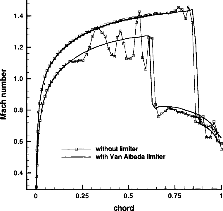
图4.10:有与无限制器的无黏跨声速流动计算比较。NACA 0012翼型,\(M_\infty\) = 0.85,\(\alpha\) = 1°。图例:纵轴为马赫数(Mach number)ï¼横轴为弦向位置(chord);带空心方块的折线为无限制器(without limiter)的结果ï¼实线为采用Van Albada限制器(with Van Albada limiter)的结果。
然而ï¼根据Godunov定理ï¼高阶线性格式(如MUSCL方法)不可能保持单调性[90]。因此ï¼必须采用非线性限制器函数来构造保持单调性或TVD的离散。图4.10演示了这一点:用方程(4.98)的上风TVD格式ï¼分别在有与无限制器的条件下计算NACA 0012翼型的二维跨声速流动。可以清楚看到ï¼无限制器时ï¼解在翼型上、下表面激波附近出现大幅振荡;而在远离激波处ï¼带限制器与不带限制器的解几乎相同。en
However, due to Godunov's theorem there is no possibility for a higher-order linear scheme (such as the MUSCL approach) to be monotonicity preserving [90]. It is therefore necessary to employ non-linear limiter functions in order to construct a monotonicity preserving or a TVD discretisation. This is demonstrated in Fig. 4.10, where the upwind TVD scheme of Eq. (4.98) was used with and without a limiter to compute 2-D transonic flow past the NACA 0012 airfoil. It can be clearly seen that without limiter, the solution exhibits large oscillations in the neighbourhood of the shocks on the upper and the lower side of the airfoil. On the other hand, the limited and the unlimited solutions become nearly identical away from the shocks.
限制器的目的是减小用于把流动变量插值到控制体面的斜率(即\((U_{I+1} - U_I)/\Delta x\))ï¼以约束解的变化。在强间断处ï¼限制器必须把斜率减为零ï¼以防产生新极值。这意味着无论对MUSCL方法还是对TVD格式ï¼在大梯度的紧邻区域都退回到(单调的)一阶上风格式(方程(4.46)中\(\epsilon = 0\))。对限制器的最后一项要求显而易见——在流动光滑区域必须还原为原始的无限制离散ï¼以使数值耗散量尽可能低。限制器对左、右状态插值的影响示于图4.11。例子显示了在局部极小值\(I\)处斜率的减小ï¼以及在单元\((I+1)\)、\((I+2)\)处为获得单调解而对斜率的改变。重要的是要认识到ï¼面上左、右状态之间的差仍可能(而且一般将会)存在。en
The purpose of a limiter is to reduce the slopes (i.e., \((U_{I+1} - U_I)/\Delta x\)) used to interpolate a flow variable to the face of a control volume in order to constrain the solution variations. At strong discontinuities, the limiter has to reduce the slopes to zero to prevent the generation of new extrema. This implies for the MUSCL approach as well as for the TVD schemes that the (monotone) first-order upwind scheme (\(\epsilon = 0\) in Eq. (4.46)) is recovered in the immediate vicinity of large gradients. The last requirement to be imposed on a limiter is quite obvious - the original unlimited discretisation has to be obtained in smooth flow regions, in order to keep the amount of numerical dissipation as low as possible. The effect of a limiter on the interpolation of the left and right states is sketched in Fig. 4.11. The example shows the slope reduction at the local minimum at \(I\) and the change of the slope at the cells \((I+1)\), \((I+2)\) to achieve a monotone solution. It is important to realise that a difference between the left and right state at a face may (and generally will) still be present.
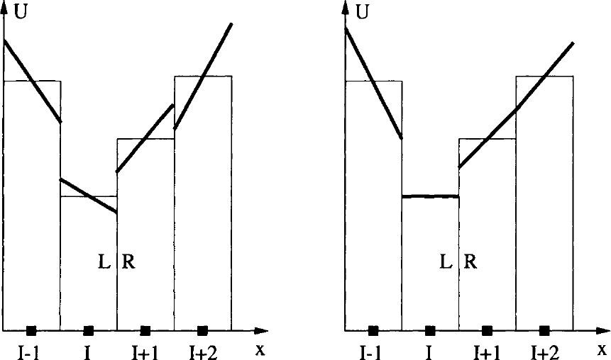
图4.11:向单元面直接插值(左)与限制插值(右)的比较。图例:粗线表示斜率\(\Delta U/\Delta x\)ï¼竖条表示单元中心处的值;横轴为\(I-1\)、\(I\)、\(I+1\)、\(I+2\)与\(x\),L、R标记面上的左、右状态。
下面我们描述四种业已确立并经实践检验的限制器函数:分别针对二阶MUSCL、CUSP以及上风TVD格式。en
In the following, we shall describe four different limiter functions, which are well-established and proven in practice. We shall consider limiters for the second-order MUSCL, for the CUSP and for the upwind TVD scheme.
Limiter Functions for MUSCL Interpolation 用于MUSCL插值的限制器函数
Van Leer的MUSCL方法[29]通过在必要时用限制器函数缩小方程(4.47)中的差分\(\Delta_{+}U_I\)与\(\Delta_{-}U_I\)ï¼即可成为保持单调性的格式。引入斜率限制器(slope limiter)\(\Phi^{\pm}\)后ï¼方程(4.46)中的MUSCL插值公式修改如下(另见图4.8)en
Van Leer's MUSCL approach [29] is turned into a monotonicity preserving scheme by employing a limiter function to reduce the differences \(\Delta_{+}U_I\) and \(\Delta_{-}U_I\) in Eq. (4.47) when necessary. Introducing slope limiters \(\Phi^{\pm}\), the MUSCL interpolation formulae in Eq. (4.46) are modified as follows (see also Fig. 4.8)
方程(4.46)中的参数\(\epsilon\)取为1。斜率限制器是相邻解变分之比的函数ï¼即\(\Phi^{\pm}_{I+1/2} = \Phi(r^{\pm}_{I+1/2})\)ï¼其定义[1]为en
The parameter \(\epsilon\) in Eq. (4.46) was set equal to unity. The slope limiters are functions of the ratios of the consecutive solution variations, i.e., \(\Phi^{\pm}_{I+1/2} = \Phi(r^{\pm}_{I+1/2})\), with the definitions [1]
若现在以\(r_L\)替代\(r^{+}_{I-1/2}\)、以\(r_R\)替代\(r^{-}_{I+3/2}\)ï¼即en
If we substitute now \(r_L\) for \(r^{+}_{I-1/2}\) and \(r_R\) for \(r^{-}_{I+3/2}\), thus
其中限制器函数(limiter function)定义为en
with the limiter function defined as
方程(4.110)中斜率限制器\(\Phi\)现在可以有不同的表述ï¼可针对特定的\(\hat{\kappa}\)值加以定制ï¼以得到最精确同时稳定且保持单调性的MUSCL格式。en
Different formulations of the slope limiter \(\Phi\) in Eq. (4.110) are now possible, which can be tailored to specific values of \(\hat{\kappa}\) to give the most accurate but stable and monotonicity preserving MUSCL scheme.
MUSCL scheme with \(\hat{\kappa}\) = 0 \(\hat{\kappa}\)=0的MUSCL格式
对\(\hat{\kappa} = 0\)的二阶上风偏置格式ï¼一种特别合适的组合是[92]en
One particularly suitable combination for the second-order, upwind-biased scheme with \(\hat{\kappa} = 0\) is [92]
此时ï¼函数\(\Psi(r)\)对应于Van Albada限制器[93]en
In this case, the function \(\Psi(r)\) corresponds to the Van Albada limiter [93]
函数\(\delta\)对两种状态在形式上完全相同ï¼即en
The function \(\delta\) is formally identical for both states. It reads
系数\(a\)与\(b\)对左、右状态定义为en
The coefficients \(a\) and \(b\) are defined for the left and right state as
差分算子\(\Delta_{\pm}\)由方程(4.47)给出。方程(4.114)中的附加参数\(\epsilon\)防止限制器在流动光滑区域因小尺度振荡而被激活[92];为获得完全收敛的定常解ï¼有时需要这样做。参数\(\epsilon\)宜取为与当地网格尺度成比例ï¼例如三维中取\(\Omega^{1/3}\)[92]、[94]。若状态变量\(U\)以物理单位给出ï¼则参数\(\epsilon\)还需附加缩放。可以证明ï¼对光滑变化的流动ï¼方程(4.113)的关系式与\(\hat{\kappa} = 0\)的原始(无限制)MUSCL格式(4.46)完全相同ï¼因此解的精度不受影响;另一方面ï¼函数\(\delta\)在局部极值处变为零ï¼如所期望地把精度降为一阶。en
and the difference operators \(\Delta_{\pm}\) are given by Eq. (4.47). The additional parameter \(\epsilon\) in Eq. (4.114) prevents the activation of the limiter in smooth flow regions due to small-scale oscillations [92]. This is sometimes necessary in order to achieve a fully converged steady-state solution. The parameter \(\epsilon\) is conveniently set proportional to the local grid scale, in 3D for example to \(\Omega^{1/3}\) [92], [94]. Additional scaling of the parameter \(\epsilon\) is required if the particular state variable \(U\) is given in physical units. It can be shown that the relations in Eq. (4.113) are identical to the original (unlimited) MUSCL scheme (4.46) with \(\hat{\kappa} = 0\) for smoothly varying flow. Thus, the accuracy of the solution is not influenced. On the other hand, the function \(\delta\) becomes zero at local extrema, reducing the accuracy to first order as desired.
MUSCL scheme with \(\hat{\kappa}\) = 1/3 \(\hat{\kappa}\)=1/3的MUSCL格式
针对\(\hat{\kappa} = 1/3\)的三点二阶精度上风偏置MUSCL格式ï¼设计了另一种限制器函数。此时斜率限制器为en
Another limiter function was devised for the three-point, second-order accurate upwind-biased MUSCL scheme with \(\hat{\kappa} = 1/3\). Here, the slope limiter is given by
此时ï¼函数\(\Psi(r)\)对应于Hemker与Koren的限制器[95]。按照与前一种情形相同的步骤ï¼得到的面\((I+1/2)\)处左、右状态公式与方程(4.113)相同ï¼只是\(\delta\)改为[92]en
In this case, the function \(\Psi(r)\) corresponds to the limiter of Hemker and Koren [95]. Following the same way as in the previous case, we obtain formulae for the left and right state at the face \((I+1/2)\) which are identical to Eq. (4.113), but now with [92]
系数\(a\)、\(b\)以及参数\(\epsilon\)的定义保持不变。en
The definitions of the coefficients \(a\), \(b\), and of the parameter \(\epsilon\) are retained.
Limiter for CUSP Scheme CUSP格式的限制器
在CUSP格式(4.3.2小节)框架下ï¼左(\(L\))、右(\(R\))状态按[43]以二阶精度计算en
In the framework of the CUSP scheme (Subsection 4.3.2), the left (\(L\)) and right (\(R\)) states are evaluated to second-order accuracy according to [43]
其中en
where
限制器本身定义为en
respectively. The limiter itself is defined as
其中\(\sigma\)为正常系数ï¼通常取2。常数\(\epsilon\)用于防止除零(例如\(\epsilon = 10^{-20}\))。若\(\Delta_1\)与\(\Delta_2\)恰好符号相反、大小相同ï¼则限制器变为\(\Psi = 0\)ï¼这意味着左、右状态只能得到一阶精度近似。en
where \(\sigma\) is a positive coefficient which is usually set equal to two. The constant \(\epsilon\) is required to prevent division by zero (e.g., \(\epsilon = 10^{-20}\)). If \(\Delta_1\) and \(\Delta_2\) happen to have opposite sign but the same magnitude, the limiter becomes \(\Psi = 0\). This means that we obtain only a first-order accurate approximation for the left and the right state.
应当指出ï¼也可以不用上述关系ï¼而代之以\(\hat{\kappa} = 0\)并采用方程(4.113)-(4.115)中Van Albada限制器的MUSCL格式。en
It should be mentioned that it is also possible to employ the MUSCL scheme with \(\hat{\kappa} = 0\) and the Van Albada limiter from Eqs. (4.113)-(4.115) instead of the above relations.
Limiter for TVD Scheme TVD格式的限制器
与前几种情形相比ï¼这里的限制器不作用于守恒变量或原始变量ï¼而是作用于特征变量\(\vec{C}\)。一种特别合适的限制器函数由[84]给出en
In comparison to the previous cases, the limiter here acts not on the conservative or the primitive variables, but on the characteristic variables \(\vec{C}\). One particularly suitable limiter function is given by [84]
其中\(\Delta C^{l}_{I+1/2}\)表示控制体面\((I+1/2)\)处特征变量之差(方程(4.101))。分母中的正常数\(\epsilon \approx 10^{-20}\)防止除零。在高梯度区域ï¼限制器函数变为零ï¼由方程(4.99)与方程(4.98)导致一阶精度的上风格式。当流动变量光滑变化时ï¼方程(4.98)的上风TVD格式保持二阶精度ï¼此时\(\Psi^{l}_{I} = C^{l}_{I} - C^{l}_{I-1}\)。en
where the \(\Delta C^{l}_{I+1/2}\) represents the difference of the characteristic variables at face \((I+1/2)\) of the control volume (Eq. (4.101)). The positive constant \(\epsilon \approx 10^{-20}\) in the denominator prevents division by zero. In regions with high gradients, the limiter function becomes zero, which leads with Eq. (4.99) and Eq. (4.98) to first-order accurate upwind scheme. The upwind TVD scheme in Eq. (4.98) retains second-order accuracy in areas with smoothly varying flow variables, where \(\Psi^{l}_{I} = C^{l}_{I} - C^{l}_{I-1}\).